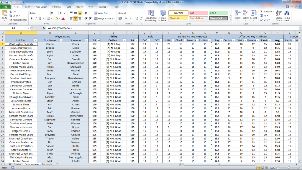
Incompatible records and spreadsheet confusion Part of the problem is that a complete set of documents includes files with multiple, incompatible formats. Office area blueprints showing the location of wiring closets, patch panels, cable trays and connection jacks are often AutoCAD files. Excel spreadsheets are often used to keep track of which PC connects to which jack, which connects to which, which, in turn, connects to which switch port. Free Download Nikon Ne 20s Owners Manual Programs.

There is no way to relate the two files to each other to provide an easy way to see the physical location of a connection point. Another problem with spreadsheets is the lack of internal consistency checking. When moving multiple PCs to different jacks, you might miss entering one of the changes in the spreadsheet. The result could be that your documentation would show two PCs connected to the same jack. Nor are end-to-end connections obvious in a spreadsheet. If your spreadsheet has a line item for each PC-to-jack connection, each jack-to-patch panel connection, and each patch panel-to-switch port connection, the relationship between a PC and switch port requires locating three different line items.
Tracking cabling with dedicated software Cable management software packages are designed to address these problems. They integrate information from blueprints with information about connections, maintain internal consistency (preventing errors such as two PCs connected to the same jack), and make both individual and end-to-end connections easy to see. Such packages include by Total Wire Software Company Inc. And by Brady. This software can import connection information from Excel spreadsheets and maintain internal consistency of the data. Both integrate with Visio to read and update building or office area blueprints.
Latest trending topics being covered on ZDNet including Reviews, Tech Industry, Security, Hardware, Apple, and Windows. Oct 14, 2013. I wondered, is there a standard way of representing the way ports are patched up, that is easy to document and update. Of course a spreadsheet springs to mind and this will be the default choice, but I wondered if there is a better way. Patch panel Ports 1. Green cable plugs into Netgear swtich Port4 2.
They integrate the two types of data by providing a way for you to add physical connection point locations to the blueprint. Both products are compatible with the ANSI/TIA/EIA-606A standard. This standard specifies formats and required information for identifying and describing cabling elements such as, telecommunications spaces and endpoint locations. UltiCAM 2000 allows you to describe a network change and then request a printed work order. The work order describes to a technician the steps to be performed to carry out the change. When the work is done, you specify to UltiCAM that the change is now complete.
At that point, the product updates its database to reflect the change. NetDoc interfaces with Brady's software to create labels that then can be printed and attached to cables, wall jacks, and so on. Use of compatible cable management and labeling software ensures that identifiers in the documentation will exactly match the label attached to the object. Finally, cable management software makes updating documentation a quick and easy process, increasing the likelihood that the task will actually be done. But don't wait for an emergency.
The best time to install and begin using cable management software is when the network is first installed. If that time has passed, make the necessary effort now, before an emergency.
About the author: David B. Jacobs has more than 20 years of networking industry experience. He has managed leading-edge software development projects and consulted to Fortune 500 companies as well as software startups.